Page 23 of 529
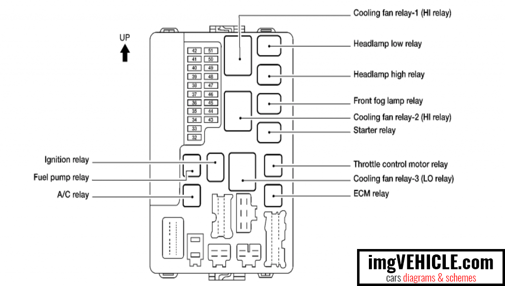
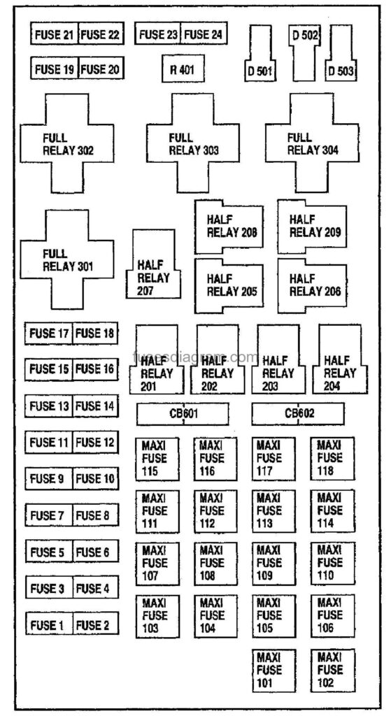
Control Master DX Manual for Sentry 2.0. Controller Instructions. CS-26, CS-4426 & CS-5630 Glass Kiln Latch Installation Instructions. Service Bulletins. Dawson Models P & K Kiln Sitter Operating Instructions. Exposure Lights FUSE Manuals & User Guides. User Manuals, Guides and Specifications for your Exposure Lights FUSE Flashlight. Database contains 1 Exposure Lights FUSE Manuals (available for free online viewing or downloading in PDF): Operation & user’s manual.

0-10Illustrated table of contents
WAA0133X
1. Side ventilator (P.4-27)
2. Meters and gauges (P.2-6)
3. Hazard warning flasher switch (P.6-2)
4. Center ventilator (P.4-27)
5. Upper touch screen display (upper dis-play) (See INFINITI InTouch
TMOwner’s Manual.)
— Around View
®Monitor (P.4-3)
— Navigation system (See INFINITI
InTouch
TMOwner’s Manual.) 6. Lower touch screen display (lower dis-
play) (See INFINITI InTouch
TMOwner’s
Manual.)
7. Heater and air conditioner control (P.4-28)
— Heated seats switch (P.2-48)
— Climate controlled seats switch (if so
equipped) (P.2-50)
— Defroster switch (P.2-39)
8. Front passenger air bag status light (P.1-60)
9. Audio system (See INFINITI InTouch
TM
Owner’s Manual.)
10. Front passenger supplemental air bag (P.1-52)
11. Fuse box (P.8-20)
12. Parking brake (P.5-22)
13. Hood release handle (P.3-21)
14. Steering wheel — Horn (P.2-48)
— Driver supplemental air bag (P.1-52)
— Power steering system (P.5-123)
15. Push-button ignition switch (P.5-12)
16. Front console — Power outlet (P.2-56)
— USB connection port (See Infiniti
InTouch Owner’s Manual.)
INSTRUMENT PANEL
Page 102 of 529
WAA0133X
1. Side ventilator
2. Meters and gauges
3. Hazard warning flasher switch
4. Center ventilator5. Upper touch screen display (upper dis-
play)
— Around View
®Monitor
— Navigation system
6. Lower touch screen display (lower dis- play) 7. Heater and air conditioner control
— Heated seats switch
— Climate controlled seats switch (if so
equipped)
— Defroster switch
8. Front passenger air bag status light
9. Audio system
10. Front passenger supplemental air bag
11. Fuse box
12. Parking brake
13. Hood release handle
14. Steering wheel — Horn
— Driver supplemental air bag
— Power steering system
15. Push-button ignition switch
16. Front console — Power outlet
— USB connection port
17. Cup holder/Tray
18. Glove box
Instruments and controls2-5
INSTRUMENT PANEL

Page 154 of 529
SIC4391
Luggage room
Type A (if so equipped)
The power outlet is used for powering
electrical accessories such as cellular tele-
phones.
CAUTION
. The outlet and plug may be hot
during or immediately after use.
. Do not use with accessories that
exceed a combined power draw of
12 volts, 120W (10A) for all the
power outlets. Do not use double
adapters or more than one electrical accessory.
. This power outlet is not designed for
use with a cigarette lighter unit.
. Push the plug in as far as it will go. If
good contact is not made, the plug
may overheat or the internal tem-
perature fuse may blow.
SIC2648
Main switch
Type B (if so equipped)
The power outlet (plug type) is located on
the back side of the front console. It can
operate when the ignition switch in the ON
position and the main switch (located in the
console box) is ON.
The specification of this power outlet is for
use of a 120 volt, 150W (1.25A) power
draw.
To turn on or off the power supply to the
outlet, push the ON
or OFFside of the
main switch. When the switch is turned to
the ON position, the indicator light
will
illuminate.
Instruments and controls2-57
Page 441 of 529
8-18Do-it-yourself
SDI2518
SDI2532
WAI0113X
ENGINE COMPARTMENT
WARNING
Never use a fuse of a higher or lower
amperage rating than that specified on
the fuse box cover. This could damage
the electrical system or electronic con-
trol units or cause a fire.
If any electrical equipment does not operate,
check for an open fuse.
1. Be sure the ignition switch is pushed to the OFF or LOCK position and the
headlight switch is turned to OFF. 2. Open the engine hood and remove the
cover on the battery.
3. Remove the fuse/fusible link holder cover
,or.
4. Remove the fuse with the fuse puller.
FUSES
Page 442 of 529
SDI1753
Type A
SDI1754
Type B5. If the fuse is open
, replace it with a
new fuse. Spare fuses are stored in the
passenger compartment fuse box.
6. If a new fuse also opens, have the electrical system checked and repaired.
It is recommended you visit an INFINITI
retailer for this service.
Fusible links
If any electrical equipment does not operate
and fuses are in good condition, check the
fusible links. If any of these fusible links are
melted, replace only with genuine INFINITI
parts.
Do-it-yourself8-19
Page 443 of 529

Mio Fuse Manual
8-20Do-it-yourself
JVM0200X
PASSENGER COMPARTMENT
WARNING
Never use a fuse of a higher or lower
amperage rating than that specified on
the fuse box cover. This could damage
the electrical system or electronic con-
trol units or cause a fire.
If any electrical equipment does not operate,
check for an open fuse.
1. Be sure the ignition switch is pushed to the OFF or LOCK position and the
headlight switch is turned to OFF. 2. Open the fuse box lid.
3. Remove the fuse with the fuse puller
.
4. If the fuse is open, replace it with a new fuse.
5. If a new fuse also opens, have the electrical system checked and repaired.
It is recommended you visit an INFINITI
retailer for this service. Spare fuses are
stored in the fuse box.
SDI2704
Extended storage fuse switch (if so
equipped)
To reduce battery drain, the extended
storage fuse switch comes from the factory
switched off. Prior to delivery of your
vehicle, the switch is pushed in (switched
on) and should always remain on.
If the extended storage fuse switch is not
pushed in (switched on), the “Shipping Mode
On, Push Storage Fuse” warning may appear
on the vehicle information display. See
“Vehicle information display” (P.2-20).
If any electrical equipment does not operate,
remove the extended storage fuse switch
and check for an open fuse.
Page 444 of 529
Winnebago Fuse Manual

NOTE:
If the extended storage fuse switch mal-
functions or if the fuse is open, it is not
necessary to replace the switch. In this case,
remove the extended storage fuse switch
and replace it with a new fuse of the same
rating.
How to remove the extended storage fuse
switch:
1. To remove the extended storage fuseswitch, be sure the ignition switch is in
the OFF or LOCK position.
2. Be sure the headlight switch is in the OFF position.
3. Remove the fuse box cover.
4. Pinch the locking tabs
found on each
side of the storage fuse switch.
5. Pull the storage fuse switch straight out from the fuse box
.
CAUTION
Be careful not to allow children to
swallow the battery and removed parts.
SDI2451
Replace the battery as follows:
1. Release the lock knob at the back of theIntelligent Key and remove the mechan-
ical key.
2. Insert a small screwdriver into the slit of the corner and twist it to separate the
upper part from the lower part. Use a
Do-it-yourself8-21
INTELLIGENT KEY BATTERY
REPLACEMENT
2006 Honda Odyssey Fuse Manual Diagram
Page 520 of 529
F
F.M.V.S.S./C.M.V.S.S. certification label .... 10-12
FilterAir cleaner housing filter ............................. 8-14
Changing engine oil and filter ...................... 8-6
Flashers (See hazard warning
flasher switch) ......................................................... 6-2
Flat tire ...................................................................... 6-3
Flat towing .......................................................... 10-31
Flexible seating .................................................... 1-10
Floor mat cleaning ................................................. 7-6
Fluid Automatic Transmission Fluid (ATF) ......... 8-8
Brake fluid ......................................................... 8-9
Capacities and
recommended fluids/lubricants ................. 10-2
Engine coolant .................................................. 8-4
Engine oil ........................................................... 8-6
Power steering fluid ....................................... 8-8
Window washer fluid .................................. 8-10
Fog light switch ................................................... 2-47
Forward Emergency Braking (FEB) with
pedestrian detection system ............................ 5-95
Forward Emergency Braking system
warning light ......................................................... 2-16
Front passenger air bag and status light ..... 1-60
Front power seat adjustment ............................. 1-4
Front seat Front seat adjustment ........................ 1-4, 1-10
Front-seat active head restraint ...................... 1-17 Fuel
Capacities and
recommended fluids/lubricants ................. 10-2
Fuel economy ............................................... 5-113
Fuel information ........................................... 10-4
Fuel octane rating ........................................ 10-4
Fuel-filler cap .................................................. 3-26
Fuel-filler door ............................................... 3-26
Gauge .................................................................. 2-9
Loose Fuel Cap warning ............................. 3-28
Fuel efficient driving tips ................................. 5-112
Fuses ....................................................................... 8-18
Fusible links ........................................................... 8-19
G
Garage door opener HomeLink®
Universal Transceiver ....................... 2-75, 2-79
Gas cap ................................................................... 3-26
Gauge ........................................................................
. 2-6 Engine coolant temperature gauge ............ 2-8
Engine oil pressure gauge ............................. 2-9
Fuel gauge ......................................................... 2-9
Odometer ............................................................ 2-7
Speedometer ...................................................... 2-7
Tachometer ....................................................... 2-8
Trip computer ................................................. 2-31
General maintenance ............................................. 9-2
Glove box ............................................................... 2-63
H
Hazard warning flasher switch ........................... 6-2
Head restraints/headrests ................................ 1-13
Headlight washer ................................................ 2-45
Headlights Aiming control ............................................... 2-44
Aiming control (See adaptive front
lighting system (AFS)) .................................. 2-45
Bulb replacement .......................................... 8-24
Headlight switch ........................................... 2-40
Heated seats ......................................................... 2-48
Heated steering wheel ....................................... 2-47
Heater Automatic climate control ......................... 4-28
Engine block heater .................................... 5-129
High beam assist ................................................. 2-41
Hill start assist system .................................... 5-120
HomeLink
®Universal Transceiver ....... 2-75, 2-79
Hood release ......................................................... 3-21
Hook Coat hooks ...................................................... 2-65
Luggage hook ................................................. 2-66
Horn ........................................................................
. 2-48
I
Ignition switch (Push-button) .......................... 5-12
Immobilizer system .............................................. 2-35
In-cabin microfilter .............................................. 4-36
Indicator
Vehicle information display ........................ 2-20
11-3